
Interactive Flat Panel in Himachal Pradesh
March 3, 2021Physics Lab Manual: How to use a Ballistic Galvanometer?
May 7, 2025Understanding Your Multimeter
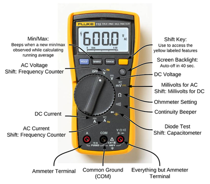
- Display: Shows the measurement values.
- Selector Knob: Used to choose the measurement type (voltage, current, resistance) and the range.
- Ports/Jacks: Where you plug in the test leads. Typically, there’s a:
- COM (Common): Usually black lead.
- VΩmA: For measuring voltage, resistance, and small currents (usually red lead).
- 10A (or similar): For measuring larger currents (usually red lead, use only when measuring high currents as indicated).
- Test Leads: Usually a red and a black wire with probes at the end.
(a) Measuring Resistances
- Turn off the power: Ensure the circuit or component you want to measure the resistance of has no power flowing through it.
- Select the Resistance mode: Turn the selector knob to the Ω (Ohm) symbol, but You might have different ranges (e.g., 200Ω, 2kΩ, 20kΩ). If you don’t know the resistance value, start with a higher range and go down if needed.
- Connect the test leads: Plug the black lead into the
COMport and the red lead into theVΩmAport. - Touch the probes: Place the probes across the component whose resistance you want to measure. Ensure good contact. Polarity doesn’t matter for resistors.
- Read the display: The multimeter will display the resistance value in Ohms (Ω), Kilohms (k$\Omega$), or Megohms (M$\Omega$), depending on the setting and the component. If the display shows “OL” or “1”, it means the resistance is higher than the selected range; try a higher range. If it shows a very low value when you expect higher, try a lower range for more precision.
(b) Measuring AC and DC Voltages
- Select the Voltage mode:
- For DC Voltage: Turn the selector knob to the V with a straight line and sometimes a dashed line (V−−−).
- For AC Voltage: Turn the selector knob to the V with a wavy line (V∼). Choose an appropriate voltage range. If you don’t know the voltage, start with the highest range and decrease it until you get a good reading.
- Connect the test leads: Plug the black lead into the
COMport and the red lead into theVΩmAport. - Connect to the circuit:
- For DC Voltage: Place the red probe on the positive (+) point and the black probe on the negative (-) point of the circuit or component you’re measuring. Reversing the leads will usually just show a negative voltage reading.
- For AC Voltage: Place the probes across the points you want to measure. Polarity does not matter for AC voltage.
- Read the display: The multimeter will display the voltage value. Make sure to note the units (V, mV, kV).
(c) Measuring DC Current
Caution: Measuring current requires you to break the circuit and put the multimeter in series. Incorrectly doing this can cause a short circuit and potentially damage your multimeter or the circuit.
- Turn off the power: Ensure the circuit is powered off before you start.
- Select the Current mode: Turn the selector knob to the A (Ampere) with a straight line (A−−−). You’ll likely have different ranges (e.g., mA, A). Choose a range that is expected to be higher than the current you’re measuring. For larger currents (usually above 200mA, check your multimeter’s manual), you might need to use the
10Aport. - Connect the test leads:
- For smaller currents (mA range): Plug the black lead into
COMand the red lead intoVΩmA. - For larger currents (up to 10A): Plug the black lead into
COMand the red lead into the10Aport (if available on your multimeter).
- For smaller currents (mA range): Plug the black lead into
- Break the circuit: You need to insert the multimeter in series with the component whose current you want to measure. This means you need to open the circuit at some point and connect the multimeter probes across the break so that the current flows through the multimeter.
- Connect the probes: Place the red probe on the side of the break that is closer to the positive side of the power source, and the black probe on the side closer to the negative side or the rest of the circuit.
- Turn on the power: Carefully turn the power to the circuit back on.
- Read the display: The multimeter will display the current value. Make sure to note the units (A, mA).
- Turn off the power: Once you’ve taken your reading, turn off the power before disconnecting the multimeter.
(d) Checking Electrical Fuses
You can check a fuse using the Continuity mode or the Resistance mode.
Using Continuity Mode (Preferred):
- Select Continuity mode: Turn the selector knob to the symbol that looks like a sound wave or a diode symbol with a sound wave next to it ($\ ))) $ or $\rightarrow | \leftarrow \ ))) $).
- Connect the test leads: Plug the black lead into
COMand the red lead intoVΩmA. - Touch the probes: Place one probe on each end (or the metallic contact points) of the fuse.
- Listen for a beep:
- If the multimeter beeps, the fuse has continuity and is likely good (the circuit inside is intact).
- If there is no beep (or the display shows “OL” or a high resistance in some multimeters in this mode), the fuse is likely blown.
Using Resistance Mode:
- Select Resistance mode: Turn the selector knob to the Ω symbol, usually on a low range (e.g., 200Ω).
- Connect the test leads: Plug the black lead into
COMand the red lead intoVΩmA. - Touch the probes: Place one probe on each end of the fuse.
- Read the display:
- A reading close to 0 Ω indicates that the fuse is good (low resistance path).
- A very high reading (like “OL” or several k$\Omega$ or M$\Omega$) indicates that the fuse is blown (broken circuit, high resistance).
Remember to always prioritize safety when working with electrical circuits. If you are unsure about any step, it’s best to consult a qualified electrician.