
Physics Lab Manual: How to use a Ballistic Galvanometer?
Physics Lab Manual: How to Use a Multimeter?
May 7, 2025How to determine hydrogen (H2) using a Orsat gas analysis apparatus?
May 26, 2025A Ballistic Galvanometer (BG) is specifically designed to measure the total charge that passes through it in a short time. Its key characteristic is a relatively long period of oscillation compared to the duration of the current pulse.
Understanding the Ballistic Galvanometer
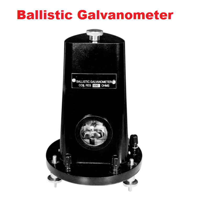
Before we proceed, remember that the deflection of a ballistic galvanometer is proportional to the total charge that flows through its coil. The relationship is given by:
q=Kθ
where:
- q is the charge that flows through the coil.
- θ is the first maximum deflection (or throw) of the galvanometer.
- K is the ballistic constant of the galvanometer.
(i) Measurement of Charge Sensitivity (Sq) and Current Sensitivity (Si)
Charge Sensitivity (Sq): It is defined as the deflection produced per unit charge passing through the galvanometer.
Sq=qθ (in radians/Coulomb or divisions/Coulomb)
Procedure:
- Calibrated Capacitor: Use a capacitor of known capacitance (C) charged to a known voltage (V). The charge on the capacitor is q=CV.
- Discharge through BG: Connect the charged capacitor to the ballistic galvanometer and discharge it through the coil. Note the first throw (θ).
- Calculate Charge Sensitivity: Sq=qθ=CVθ If θ is measured in radians, Sq will be in radians/Coulomb. If θ is measured in divisions of the scale, Sq will be in divisions/Coulomb.
Current Sensitivity (Si): It is defined as the deflection produced per unit steady current flowing through the galvanometer.
Si=Iθ (in radians/Ampere or divisions/Ampere)
To find the current sensitivity using a ballistic galvanometer, we often relate it to the charge sensitivity and the period of oscillation (T) of the galvanometer. The relationship is approximately:
Si≈T/2πSq=SqT2π
Procedure:
- Determine the period of oscillation (T): Allow the galvanometer coil to oscillate freely and measure the time taken for a known number of oscillations (e.g., 10 or 20). The period T is the total time divided by the number of oscillations.
- Use the calculated Sq and T: Calculate the current sensitivity using the formula above.
Alternatively, you can measure the steady current sensitivity directly by passing a known steady current through the galvanometer and noting the steady deflection. However, a ballistic galvanometer is optimized for charge measurement.
(ii) Measurement of Critical Damping Resistance (CDR)
The Critical Damping Resistance is the value of resistance in the galvanometer circuit that makes the deflection return to zero most quickly without oscillation.
Procedure:
- Observe Undamped Oscillations: First, ensure there is no external resistance in the galvanometer circuit (or a very high resistance). Excite the galvanometer by passing a small charge through it and observe the oscillations. Note the first throw (θ1) and subsequent throws (θ2,θ3, etc.) in the same direction.
- Introduce Resistance: Connect a variable resistance box in series with the ballistic galvanometer.
- Find Critical Damping:
- Start with a high resistance and gradually decrease it.
- For each value of resistance, excite the galvanometer and observe the nature of the deflection.
- Initially, you will see oscillations with decreasing amplitude. As you decrease the resistance, the damping will increase.
- The critical damping resistance is the value of resistance for which the galvanometer, after the initial throw, returns to its zero position most quickly without any further oscillation or overshoot. This is often identified when the subsequent throws become very small or disappear.
- Practical Determination: In practice, it might be hard to pinpoint the exact CDR. You might look for the resistance value where the ratio of successive throws (θn/θn+1) starts to decrease significantly, indicating that you are approaching overdamping. The CDR lies somewhere around the value where the oscillations are just suppressed.
A more precise method involves analyzing the logarithmic decrement of the oscillations with different damping resistances.
(iii) Determine a High Resistance by Leakage Method
The leakage method uses the discharge of a capacitor through the unknown high resistance and measures the charge remaining at different times using the ballistic galvanometer.
Procedure:
- Circuit Setup: Connect a capacitor (C) in parallel with the unknown high resistance (R). This parallel combination can be charged through a battery and a key. The galvanometer is used to measure the charge on the capacitor.
- Charging: Charge the capacitor by closing the charging circuit for a sufficient time.
- Initial Throw: Quickly disconnect the charging circuit and immediately connect the capacitor to the ballistic galvanometer to measure the initial charge (q0), which is proportional to the initial throw (θ0). So, q0=Kθ0.
- Leakage: Allow the capacitor to discharge through the high resistance R for a known time (t).
- Second Throw: After time t, quickly connect the capacitor to the ballistic galvanometer again and measure the remaining charge (qt), which is proportional to the second throw (θt). So, qt=Kθt.
The charge on the capacitor discharging through a resistance R is given by q(t)=q0e−t/RC.
Therefore, q0qt=e−t/RC
Taking the natural logarithm of both sides:
ln(q0qt)=−RCt
RC=−ln(qt/q0)t=ln(q0/qt)t
Since q∝θ, we can write:
RC=ln(θ0/θt)t
R=Cln(θ0/θt)t
By measuring θ0, θt after a time t, and knowing the capacitance C, you can determine the high resistance R.
(iv) To Determine Self Inductance of a Coil by Rayleigh’s Method
Rayleigh’s method involves comparing the throw produced in the ballistic galvanometer by the discharge of a capacitor with the throw produced by the sudden interruption of current flowing through the inductor.
Procedure:
- Circuit Setup:
- Capacitor Circuit: A capacitor (C) is charged to a known voltage (V) and can be discharged through the ballistic galvanometer.
- Inductor Circuit: The inductor (L) is connected in series with a known resistance (P) and a battery. A key allows the current to reach a steady state. This circuit can also be connected to the ballistic galvanometer to measure the effect of interrupting the current.
- Capacitor Discharge: Charge the capacitor C to voltage V and discharge it through the ballistic galvanometer. Note the first throw θ1. The charge is q=CV, and q=Kθ1, so CV=Kθ1.
- Inductor Current Interruption: Allow a steady current to flow through the inductor L and the resistance P. The steady current is I=E/P, where E is the EMF of the battery. When this current is suddenly interrupted, the induced EMF in the inductor causes a charge to flow through the galvanometer. The total charge passing through the BG is given by q′=LI/RG′, where RG′ is the total resistance in the galvanometer circuit during this measurement (including the galvanometer resistance and any series resistance). This charge q′ produces a throw θ2, so q′=Kθ2. Therefore, RG′LI=Kθ2=Kθ2. Substituting I=E/P, we get PRG′LE=Kθ2.
- Equating and Solving: We have two equations: CV=Kθ1 PRG′LE=Kθ2 Dividing the second equation by the first: PRG′CVLE=θ1θ2 L=Eθ1PRG′CVθ2 If the battery voltage E used for the inductor circuit is the same as the voltage V to which the capacitor was charged, then E=V, and: L=θ1PRG′Cθ2 To use this formula, you need to know the total resistance in the galvanometer circuit (RG′) when the inductor current is interrupted. If this is the same as the galvanometer resistance (G) when the capacitor is discharged, then RG′=G. However, the circuit configurations might differ, so be careful about this. A more refined approach in Rayleigh’s method often involves considering the damping in both cases. If the damping is small, the above approximation holds.
.